Purpose
Apply additional loads to trusses, from walls or sprinkler lines, for example. When trusses are loaded individually, it is possible to make mistakes, and some loads may be in an incorrect location or have incorrect magnitude. Applying a load via a line provides the ability to draw a line and apply a load to it; then, all of the trusses it contacts will have an accurate load at the correct location.
You can turn Load Line visibility on or off in the Layers and Filters menus.
Steps
 .
.The Wall Commands window displays.
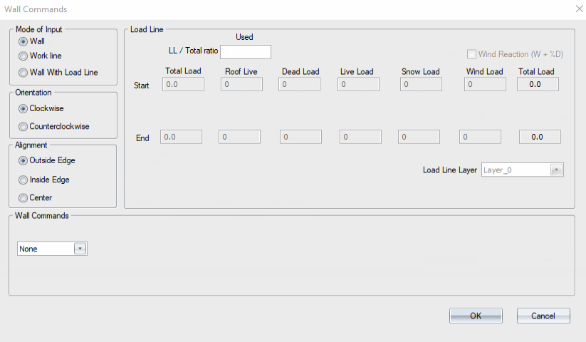
-
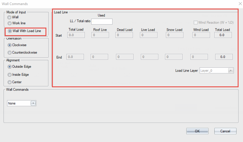
Select Wall With Load Line.
All Load Line options become active.
- Specify loads:
The LL/Total ratio is automatically populated based on the current Load Template
You can manually adjust the Live Load/Total ratio; Truss Studio uses the ratio to determine the correct distribution between Live and Dead (or Snow and Dead, or Roof Live and Dead)
Alternatively, you can enter a Total Load Start and End amount; Truss Studio automatically splits the load into appropriate parts
For a roof truss Load Template, the Total Load you enter is split into Roof Live, Dead Load, Snow Load (if enabled), and Wind Load.
For a floor truss Load Template, the Total Load you enter is split into Dead Load and Live Load.
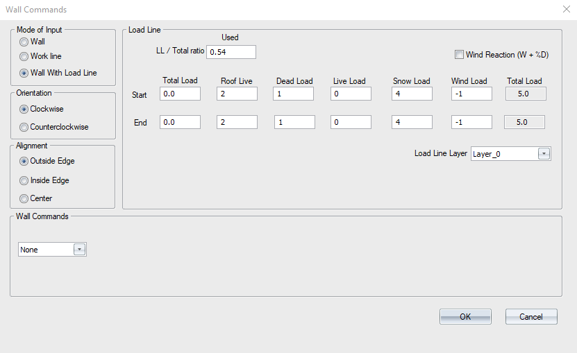
- Select the desired layer for the load line in the Load Line Layer drop down list.
-
The input loads and selected layer are displayed.
- Specify a direction and a distance in the Layout Commands box.
Letters represent a direction and a number represents a distance.
- u = up
- d = down
- l = left
- r = right

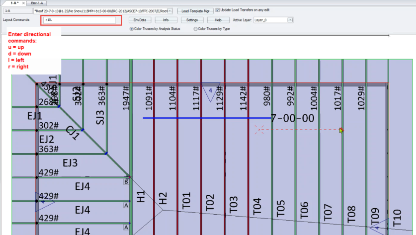
The wall is created on the active layer and a load line is created at the bottom center line of the wall.
- The load line is located on the Load Line Layer that was selected in the Wall Commands window (shown above).
- The wall and load line can be on either the same or different layers from each other.
- The load from the Load Line is transferred to the top chord of the trusses it crosses that are on the same layer as the load line.
A sample wall with load line is shown below.
The load is transferred as a point load and is displayed in the Load Transfer Point Load Dialog.
 Note: The wall and the load line are two different objects. In order to move both the wall and the load line they must first be selected before using the Move command.